
About Potentiometer-T16 and Announcement
T16 is a potentiometer developed by V&T, given the potentiometers currently on the market cannot meet the feature of s*x tech application environment. The invention of T16 is an inevitable technical route for the frequent forward and reverse commutation, high intensity use of servo motors under the current technical circumstances. Upon the full disclosure of the idea and embodiment, neither us nor other companies will be able to file patents for this technology to hinder the necessary progress of s*x tech
According to international patent law, any individual or institution (including us) apply this technology for a patent will be invalid by this disclosure.
Low Robustness of Conventional Potentiometer
In the s*x tech industry, earlier products before Syncbot had no distinct requirements for time and position accuracy. Therefore, most of the earlier products used a cheap iron core motor as the power without position feedback. Very few products use their own mechanical structure to provide a rough mechanical reset as a primitive positioning system.

Iron Core Motor for Other Players' Products
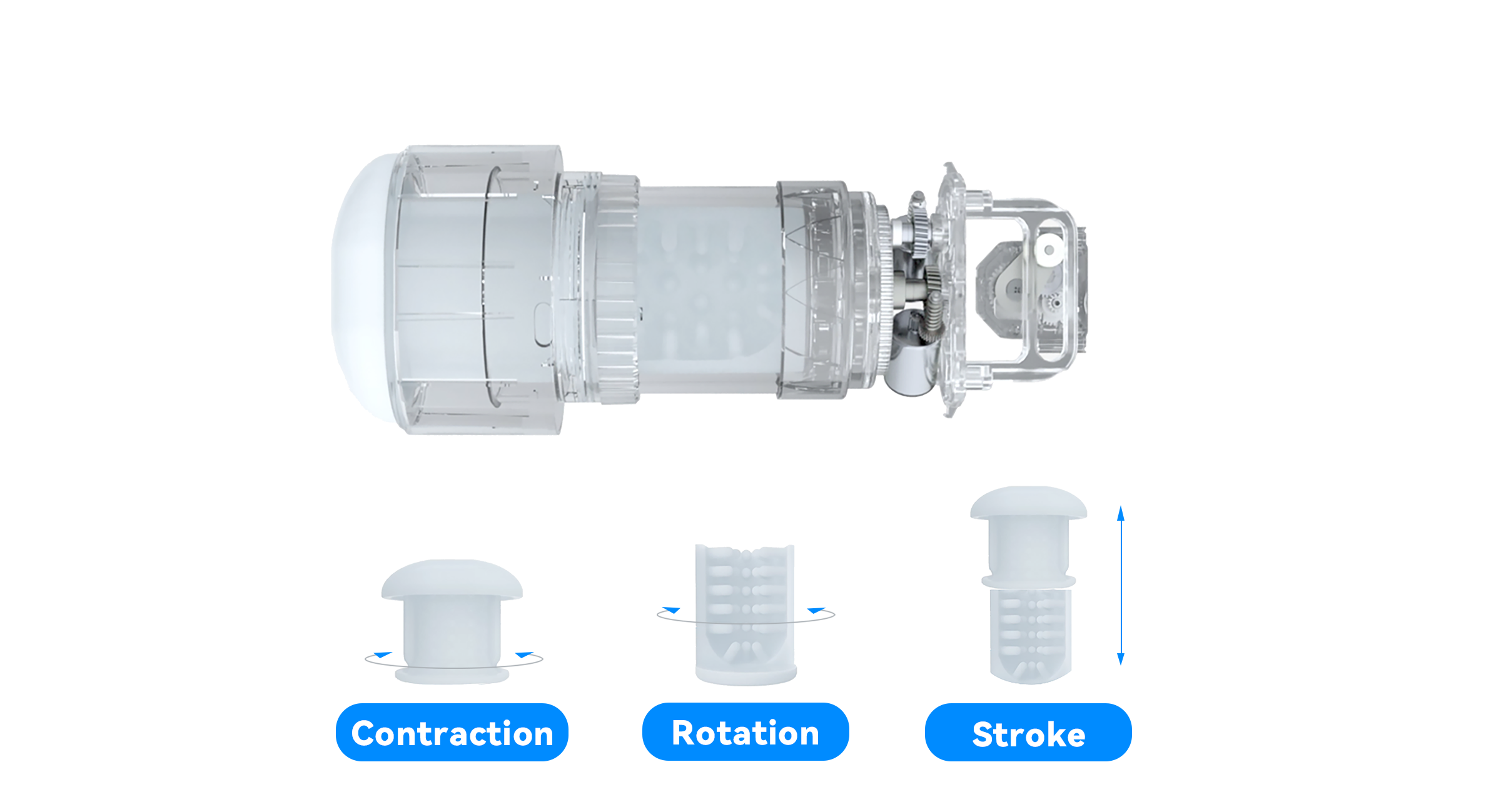
Due to Syncbot's unique feature of simultaneity and simulation, V&T have developed motors, the high-precision servo and the multi-dimensional servo that completed a new servo system, which is substantial for those features to function properly. Given the preference of the accuracy by users in the s*x tech field, two built-in potentiometer was applied to the two servos for position detection and feedback.

The Servo Motors of Syncbot
The previous potentiometer mainly serves servo rudders, servo robot joints, or servo used in drones, but has never been attempted to be applied to the requirement of s*x tech. A counter-intuitive fact is that the commutation frequency and the cumulative time of these servo motors are actually much lower than MF1867 and NT1922. To be more specific, when you are controlling a helm or rudder, its servo motor is to help modify the sailing route. During a one-hour game experience, the cumulative time for servo motor to repeatedly and severely stop and change the direction is only a few minutes in total, and there are certain intervals in those changes. However, MF1867 and NT1922 often work intensely for more than tens of minutes in a one-hour game experience, which means the stability, durability, and the robustness of the new servo system must be improved.
Our experimenting and tests before 2016 show that the conventional potentiometer was the first damaged part in the entire servo system, and most of the potentiometers on the market did not last very long as one may expect. Many of them have only been tested for hours, or even minutes, before they wear out.
We've analyzed a number of failed potentiometers on supply chain and found that the first damaged part was highly consistent.
When disassembled and observed, it can be found that the insulated solder-mask on the side of the PCBA near the magnet has been wiped off a lot, exposing the yellow copper routes and vias. The below picture of PCBA situation we saw after disassembling, suggests that followed with the failed potentiometers is the visible area of the insulated solder-mask has been scraped off, exposing the copper.

The reason behind this symptom is that designing works in ideal cases could be perfectly arranged, but the actual manufacturing will encounter the constraints of the realistic engineering processing.
On the blueprint, almost all the built-in magnets of the potentiometer will not be in direct contact with the PCB, and the designer will leave a small gap between them. However, the built-in magnets need to rotate during operation, which will inevitably cause the shaft to drive the rotating magnet and its plastic shell to scratch the PCB. While potentiometer makers, like all other component makers, are the elite in manufacturing, they can manage such incidents from happening to minimum. However, as time goes by, the magnets and its plastic shell will eventually scrape off the insulated solder-mask on the PCB, exposing the copper of the routes and vias. Severe scratches will cut off routes and result in open circuit. In addition to that, the magnet is electrically conductive and will cause short to the exposed copper routes and vias. Either a short circuit or an open circuit will cause the potentiometer to fail.
Let's take T15 as an example. The red and pink pads, routes and vias are on the inner side (close to the chip) of the PCB, while the blue routes and vias are on the outer side (close to the magnet) of the PCB. These blue routes and vias are easily scratched and scraped. The small yellow circles indicate the size and position of the magnets, and the large yellow circles indicate the size and position of the plastic shell that wraps the magnets and rotates with the magnets. It can be seen as below that the rotating plastic shell will also wear the insulated solder-mask on the PCBA, which may cause an open circuit, but not a direct short circuit. Yet the wear caused by the magnet will cause both an open circuit and a short circuit.

When these potentiometers are applied to the general servo motors, due to the low working intensity of the servo motor, the wear of the magnet and its plastic shell to the PCBA is relatively slow, so potentiometer is less likely to wear out. In s*x tech applications, however, the servo motor drives the potentiometer to rotate at a high speed, and the direction is frequently reversed back and forth, so the potentiometer will quickly lose effectiveness.
The evolution of T16
We can't urge potentiometer makers to do a better job, since they've already done their best. But after analysis, it is still possible to solve this problem.
First principal thinking, as Elon Musk once said, is supposed to "boil things down to fundamental truth". The fundamental truth in this scenario is the built-in magnets of the potentiometer damaged the PCB. So even if you can't stop the built-in magnets from moving, you could still ensure the routes and vias in the PCB somehow evade the built-in magnets.
In short, there are two methods you should be trying to achieve it. On one hand, you should arrange your routes and vias to bypass the places apt to be scratched, and on the other, you should reduce the number of routes and vias as much as possible.
The fundamental reason why potentiometer have so many routes and vias is that it must be equipped with enough test points to read, write and configure various data to meet the general purpose. Taking our previous work T15 as an example, only by using three test points can the component manufacturer directly detect and correct the initial angle value on the potentiometer. Since the initial positions of the magnets of every single potentiometer are different after being mass-produced in the factory, an element level correction of initial angle value must be performed for each potentiometer.
To reduce these routes and vias, other means need to be used to configure these data - taking the initial angle value correction compensation as an example, we put this work after the assembly of the whole Syncbot. With only a little more time cost, our software team made specialized software program modules. This module is programmed into the MCU, so the detection and computing capabilities of the MCU on the Syncbot are used to correct and compensate the initial angle value, and the correction results are stored in our MCU. We developed specialized jig and fixture tool and distributed them to workers, so that they can correct and compensate the initial angle value in the final stage. In this case, having handle the two deviations of the potentiometer being installed in the servo motor and the servo motor being installed in Syncbot, the final calibration accuracy will be higher than those of the component suppliers. At the same time, we suggest that this tool should be simple enough that a worker with different language background can complete the calibration process as easily as playing Tetris.
After solving most of the problems of reading, writing and parameter configuration by other methods other than the element-level work, the burden of T16 can be minimized and reduce test points, routes and vias much more than T15. The extra space also allows engineers to better arrange the routes.
According to the above ideas, we invented the new potentiometer T16. The design diagram of an embodiment is as below.

After the optimized design, there are almost no routes and vias in the magnet rotation area. And a small number of routes on the inner layer also could bypass the center as much as possible (for which we recommend you do the same). So even if the PCBA is damaged, there will be no open circuit or short circuit caused by scratched and scarped.
We introduced the optimized PCBA design mentioned above to commission the factory to produce T16. The photo of an embodiment is as below.

Since 2016, T16 has been developed, tested, mass-produced, and used by users, and the situation where potentiometer become dysfunctional from being damaged never happen.
Specific Details for Reference
For previous potentiometers, after the magnet is fixed on the plastic shell and installed in the potentiometer, the angle deviation (Ad) will be generated between the north and south poles of the magnet and the 0° baseline of the north and south poles required by the magnetic sensor chip. Each sensor chip will output a different angle value, so it is necessary to correct the angle value output by the chip. Element level correction requires the potentiometer factory to compensate a (-Ad) value. After the compensation, when the magnet stops at the 0° baseline, the angle value output by the chip will be 0°.

New potentiometer is not opened to an element-level correction, you will be not able to directly compensate (-Ad).
You'll need to conduct the following steps for system level correction:
- Write the system-level correction module and motion adaptation module (-Aa) to the MCU in advance.
- Install the potentiometer into your servo system, and install the whole servo system into your product to generate the new error value (As).
- Connect the jig and fixture tool with your product, enter the factory mode, and send out a correction command.
- Wait for the jig and fixture robot to reset your product to the default 0° position.
- Obtain the output angle value (Ad)+(As) of the potentiometer, which is the total deviation (Aa) of the system-level angle value.
- Write this total deviation (Aa) into the MCU. (Note: Be sure to write into flash memory instead of RAM. Don't ask me why).
- After activating the motion adaptation module (-A) on the MCU, every servo activity will generate an angle value for the MCU to use the total deviation (-Aa) to do a correction and compensation, to obtain a relatively accurate angle value at the default 0° position.
Although no manufacturer has achieved the sync effect of Syncbot in terms of user experience, they are all using the same promotion claims that they are able to do what as we do in the advertising. This made us realize that they also wanted their product to perform on the same level as Syncbot does. We also realized that they would waste a lot of time and money if they rashly imitated our technical route without realizing that this route required new components. What’s more, if they don't have high durability potentiometer, their machine will break down quickly after sent to users' hand, which will reduce the overall user experience and the reputation of s*x tech industry. Therefore, we need to remind them that if they choose to develop their own servo motor, they must develop a matching potentiometer and educate them how to develop specialized potentiometer in s*x tech application environment.
Contact US
Press Contact: press-contact@syncbot.com

Leave a comment
All comments are moderated before being published.
This site is protected by reCAPTCHA and the Google Privacy Policy and Terms of Service apply.